
To set up a desktop 3D printer and complete the first print, follow the manufacturer manual from package inspection through assembly, electrical checks, slicer setup, filament loading, first-layer calibration and diagnostic review. The sections below follow that order, then consolidate the baseline you should record.
Prepare the workspace and documents
The desktop 3D printer workspace needs a stable surface, service clearance, suitable power, required ventilation and the exact manual for the model.
Read the manual before removing restraints or connecting power. Confirm the machine’s footprint with the bed at its full travel, leave access for spool loading and maintenance, and keep vents clear. A resin printer needs a different handling, washing, curing and waste plan than an FDM printer, so this guide focuses on desktop FDM setup. This footprint data is commonly available in a Desktop 3D Printer Comparison Chart.
Gather the tools listed in the manual. Common kits include hex keys and a wrench, but the supplied set differs by model. Add flush cutters for filament and a measuring tool for the diagnostic part only when those tools fit the procedure. Preparing the workspace is a crucial step when choosing a desktop 3D printer. Furthermore, reading in-depth 3D Printer Reviews helps clarify specific setup requirements for individual models.
Unbox and inspect the printer
Unboxing a desktop 3D printer starts with documenting package damage, checking the packing list and removing every shipping restraint named in the manual.
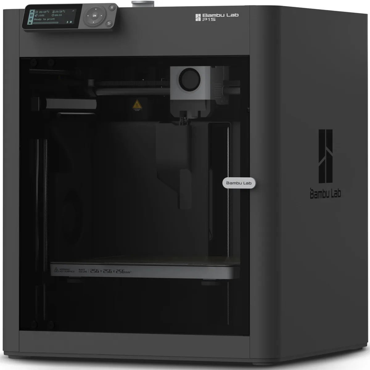
Inspect the carton for punctures, crushed corners or water damage before moving the machine. Photograph serious damage and stop if the frame, glass, wiring or enclosure appears unsafe.
Lay out the components and compare them with the packing list. Remove foam blocks, clips and cable ties from the bed, toolhead and gantry in the sequence the manual gives. Check under the build plate and around the lead screws. Do not force an axis that may still be locked for shipping.
With power disconnected, look for loose hardware inside the accessible chassis and confirm visible connectors are seated. Do not open a power supply or electronics enclosure unless the manufacturer procedure specifically requires it.
Assemble and verify the motion system
Desktop 3D printer assembly secures the frame, gantry, spool holder, display and model-specific cables before any powered motion command.
Install fasteners in the stated order and tighten them evenly. A bed-slinger gantry should sit square to the base according to the manufacturer’s alignment method. A factory-built CoreXY frame should move only as the manual permits during an unpowered check.
Inspect belts, wheels, rails and lead screws without applying a generic tension or lubricant. Belts should follow the documented path and pulleys should be secure. V-slot wheels should not wobble or bind. Linear rails and lead screws use the lubricant named by the printer maker; an unsuitable oil or grease can damage seals, collect debris or conflict with warranty instructions.
Route cables through their clips and strain reliefs. Move each allowed axis slowly through its range while the printer is unplugged and confirm that cables do not snag, stretch or rub on a sharp edge.
Complete the electrical safety checks
Electrical safety checks confirm the printer’s input-voltage setting, power cable, grounding, connectors and heater wiring before the machine is energized.
Some printers have a manual input selector labeled 115 V and 230 V. If the printer has one, set it to the value required by the manual and local supply before connecting power. Printers with automatic input selection do not need this step. Never guess from the plug shape alone.
Check the power cable and inlet for damage. Keep the printer off and unplugged while reseating user-accessible motor, endstop, fan and heater connectors named in the assembly guide. Stop setup if a connector is scorched, a wire is pinched, insulation is cut or a heater component is loose.
After power-on, stay beside the machine for the initial self-check. Stop and disconnect power if the display reports a heater fault, an axis moves against a restraint, or the machine produces smoke, sparking or an electrical odor.
Install the slicer and prepare filament
Slicer setup starts with the printer manufacturer’s current profile and a filament profile for the exact material loaded.
Install the slicer version supported by the printer maker. Select the exact printer variant, nozzle diameter and build plate. A profile for a related model can contain different machine limits or start G-code, so do not substitute it without documented compatibility.
Check for stable firmware through the manufacturer’s instructions and read the release notes before updating. Save any existing configuration or profile when the workflow permits a backup. Do not interrupt power during a firmware update.
Prepare filament according to its label or technical data sheet. Storage or drying conditions are material-specific. To load filament, heat the nozzle to the material profile’s loading temperature, cut the filament only if the manual asks for an angled end, release the extruder as directed, and extrude until the new material flows consistently. Keep hands and tools away from the hot nozzle.
Level the bed and set the first layer
Bed leveling and Z-offset calibration establish a consistent nozzle-to-surface distance before the first diagnostic print.
Clean the build surface with the method approved for that surface. Run the printer’s homing and bed-mapping routine. Automatic bed leveling measures surface variation, but some machines still require a manual Z-offset or live first-layer adjustment.
Use the paper method only when the printer manual specifies it. A sheet of paper is a repeatable contact gauge, not a universal final layer height. The How to Level a 3D Printer Bed: Paper Method and ABL guide separates manual tramming, probe mapping and first-layer verification.
During the first layer, inspect the deposited lines:
- Separate, round lines indicate that the nozzle is too far from the plate or that another adhesion condition is wrong.
- A transparent, scraped or ridged path indicates that the nozzle may be too close.
- Joined lines with consistent width indicate a usable first-layer baseline.
Pause or cancel the job before changing hardware if the nozzle contacts the surface.
Complete the first diagnostic print
The first diagnostic print should be a small, known model sliced with the current printer and material profiles.
A 20 mm XYZ calibration cube is useful because the model provides named axes, vertical walls, corners, top layers and a known nominal size. Slice the model yourself instead of relying on an unknown pre-sliced file. Use the default layer height, speed, temperature and cooling values from the supported profile.
Watch the first layer, then let the machine complete the part if adhesion and motion remain normal. Allow the build surface and part to cool according to the manual before removal.
Inspect the finished cube in this order:
- Confirm the bottom surface adhered without corner lift or nozzle damage.
- Check walls for repeating bands, shifts, gaps or ringing around corners.
- Check the top surface for unfilled gaps or excess material.
- Measure X, Y and Z with the same tool and method, then compare the result with the model.
- Record the printer profile, filament, nozzle, build surface and observed dimensions.
The acceptable dimensional deviation comes from the printer, calibration model and application requirements. This guide does not assign one universal tolerance.
Diagnose a failed first print
A failed first print should be diagnosed by symptom before changing several settings at once.
| Symptom | First checks |
|---|---|
| Printer does not start | Input setting if fitted, outlet, cable, switch and manual troubleshooting code |
| Axis cannot home | Remaining shipping restraint, connector, endstop or sensor path |
| Filament does not extrude | Load temperature, filament path, extruder grip and partial clog |
| First layer does not stick | Surface cleaning, bed mapping, Z-offset, material profile and room draft |
| Layer shift or binding | Belt path, pulley fastener, cable snag and axis obstruction |
| Rough or weak extrusion | Material condition, temperature profile, nozzle condition and feed resistance |
Change one variable, repeat the same diagnostic model and update the setup log. Multiple simultaneous changes erase the evidence that identifies the cause.
First-print baseline to keep
The first-print baseline is a documented machine state that you can return to after maintenance, transport, firmware changes or a failed profile.
Save the working slicer profile, firmware version, filament identity, first-layer setting, calibration result and photographs of the completed diagnostic part. Record any assembly correction that the manual required. The 3D printer maintenance checklist uses that baseline to distinguish normal wear from a new setup error.
A desktop 3D printer is ready for regular use when its assembly is secure, electrical checks pass, the supported profile completes a diagnostic print and the recorded result meets the project’s requirements. That sequence completes the setup query without treating one successful decorative model as proof that every material and geometry is ready.