
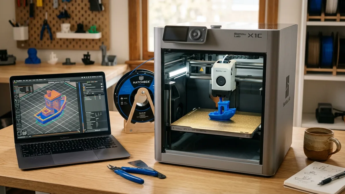
Proper part orientation involves positioning a 3D model on the build plate to maximize mechanical strength, minimize support structures, and ensure reliable bed adhesion. This guide explains the physics of part orientation in FDM, details technical settings for support structures, covers first-layer adhesion techniques, and outlines a decision framework pre-flight checklist. Hitting “print” and walking away is a rookie move; the most critical decisions happen before the nozzle heats up. How you place a part on the build plate dictates its strength, its finish, and whether it even finishes printing at all.
Get it wrong, and you get a box of plastic spaghetti. Get it right, and you produce a functional, reliable part. Let’s break down the science of part setup.
The Physics of Part Orientation in FDM
The physics of part orientation in FDM are governed by anisotropy, meaning the bond between layers is always weaker than the continuous extrusion of a single layer. Every FDM print has this hidden weakness, and it is the single most important factor in part orientation.
Anisotropy and Mechanical Strength
Anisotropy affects mechanical strength because an FDM print acts like a stack of paper glued together. You can bend the whole stack, but it’s very easy to peel one sheet off the top. Your 3D prints work the same way.
- Tensile Strength: This is a pulling force. If you print a hook standing up, the load will pull the layers apart. It will fail quickly. If you print that same hook lying on its side, the force is distributed along the length of the continuous extruded lines. This orientation is exponentially stronger. Rule: Always orient parts so tensile forces act along the XY-plane, not the Z-axis.
- Bending and Shear Forces: For parts like brackets or levers, the same logic applies. A bracket printed flat on the bed will be much stronger than one printed vertically. The force is distributed across many strong layers instead of trying to snap a few weak layer-to-layer bonds.
Surface Quality and Overhangs
Orientation directly controls surface quality and how overhangs are printed on your final part.
- The Staircase Effect: Curved or sloped surfaces that are nearly horizontal will show pronounced layer lines, often called “stair-stepping.” To get the smoothest dome, you print it with the top of the dome pointing straight up. Orient your part to place critical cosmetic surfaces either perfectly vertical or perfectly horizontal to minimize these artifacts.
- Overhangs: Most printers can handle overhangs up to 45 degrees without supports. As the angle gets steeper, the layers have less to sit on, and the print quality degrades into droopy, ugly lines. By rotating your part in the slicer, you can often eliminate the need for supports entirely. Before adding supports, always ask: can I turn this model to make that overhang a self-supporting 45-degree slope?
A Technical Guide to Support Structures
Support structures are temporary printed scaffolding required to hold up overhangs exceeding 45 degrees, though they use extra material and add print time. The goal is to use them intelligently, not just click “Generate Supports” and hope for the best.
Support Types: Standard vs. Tree
Slicers typically offer two main support types, standard and tree:
- Standard (Grid/Lines): These are vertical pillars projected down from overhangs. They are stable and reliable for large, flat overhangs. However, they can be a nightmare to remove from complex models and can scar the surface where they touch.
- Tree (Organic): Popularized by Cura and now standard in PrusaSlicer and Orca Slicer, these supports grow like tree branches from the build plate to touch the model only where needed. They use less material, print faster, and are far easier to remove. For organic shapes, figures, and complex geometries, tree supports are the superior choice.
Critical Support Slicer Settings
Critical support slicer settings must be tuned for your specific material to balance support stability with easy removal. Adjust the following configurations to optimize the interface between the support and the printed part:
| Setting | What It Does | Recommended Value |
|---|---|---|
| Support Z Distance | The vertical gap between the support and the model. | 0.2mm (PLA), 0.25-0.3mm (PETG/ABS) |
| Support XY Distance | The horizontal gap between the support and the model. | 0.5-0.7mm |
| Support Interface | Creates a dense “skin” on top of the supports for a cleaner surface. | Enable, 3-5 layers, 0mm Z-gap |
| Support Density | The infill of the support structure. | 10-20% (Tree), 20-30% (Grid) |
The Support Z Distance is the most important setting for easy removal. Too small, and the support fuses to your part. Too large, and the overhanging surface will be droopy and rough. A 0.2mm gap, equivalent to one layer height, is a standard recommended starting point for PLA.
For materials that bond aggressively, such as PETG, a larger gap of 0.25mm or even 0.3mm helps keep the support from welding itself to the main body.

Creality Space Pi Filament Dryer
Pros
- Eliminates poor layer adhesion and stringing caused by wet filament.
- PTC heating is more efficient and consistent than a basic hot plate.
- Critical for printing hygroscopic materials like Nylon, PETG, and TPU.
Cons
- Only holds one spool at a time.
Poor layer adhesion is often blamed on temperature or speed, but the real culprit is frequently moisture. Hygroscopic filaments like PETG, TPU, ABS, and Nylon absorb water from the air. When printed, this water turns to steam in the nozzle, causing pops, voids, and terrible layer-to-layer bonding. A dedicated filament dryer like the Creality Space Pi is not an optional accessory; it’s a core piece of workshop equipment for anyone serious about print quality and strength. Dry filament is the foundation for good adhesion.
First-Layer Adhesion: Your Print’s Foundation
First-layer adhesion forms the foundation of your print, as a part that unsticks from the bed will fail. Securing that first layer requires a combination of physical prep and slicer settings. For a deep dive into the initial setup, our 3D printer setup guide covers bed leveling in detail.
Adhesion Helpers: Brim, Skirt, and Raft
Slicers provide three primary adhesion helpers to prime the nozzle and secure the part to the build plate:
- Skirt: A few outlines drawn around the part without touching it. This primes the nozzle and confirms filament flow before the real print begins. Use it on every print.
- Brim: A single-layer extension connected to the base of your print. It dramatically increases the surface area touching the bed, providing powerful resistance to warping. Use a 4-8mm brim for tall, thin parts or materials like ABS and ASA that tend to shrink and lift at the corners.
- Raft: A thick grid that prints first, with your part then printed on top of it. A raft provides a perfect, disposable print surface. Use it as a last resort for extremely warp-prone materials on an open-air printer, or for models that have a very complex and tiny footprint on the bed. They consume significant time and material.
Build Plate Layout and Batch Efficiency
Build plate layout and batch efficiency require balancing the speed of printing multiple parts against the risk of a single failure ruining the entire batch. Consider these layout strategies for efficient batch printing:
- Sequential Printing: This feature, available in most modern slicers, prints each object one by one. This is a huge advantage. It eliminates stringing between parts and means that if one object fails, it doesn’t cause a catastrophic “spaghetti” failure that ruins the entire batch. The only constraint is ensuring the printhead and gantry can clear the height of the already-finished parts.
- Heat Management: Don’t cluster all your parts in the dead center. Spreading them out allows for more even heat distribution across the bed, reducing the chances of a localized hot spot causing warping. For large batches on a high-speed machine, this becomes very important.
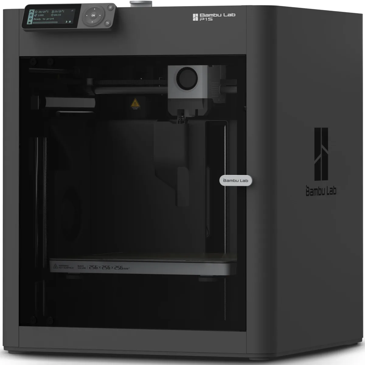
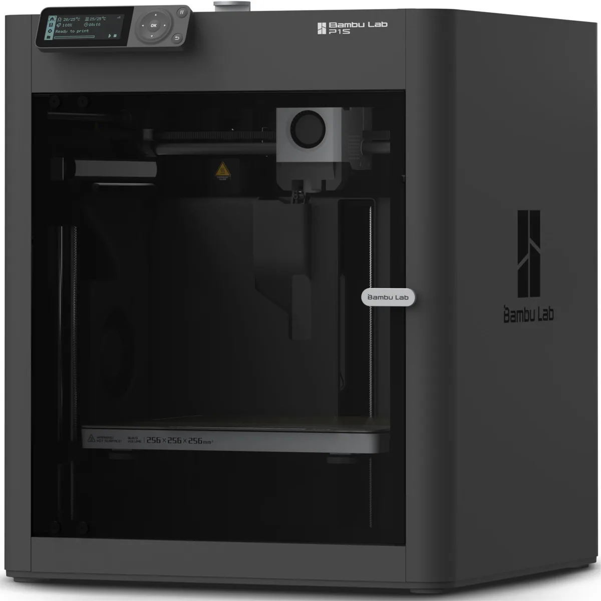
Bambu Lab P1S Enclosed 3D Printer
Pros
- Fully enclosed CoreXY chassis with auxiliary cooling fan, Smooth multi-color / multi-material integration with Bambu AMS, Reliable out-of-the-box first layers with dual automated bed leveling, Active vibration compensation and belt tension monitoring
- High-speed CoreXY kinematics reduce print times for batches.
- Textured PEI plate provides great adhesion without glue.
Cons
- Proprietary closed ecosystem
- Chamber is passively heated by the bed rather than a dedicated PTC heater
- Upgrading to hardened nozzle for carbon fiber requires separate swap
When you move from single prints to batch production, speed and reliability are key. A printer like the Bambu Lab P1S changes the calculation. Its enclosed frame provides a stable, heated environment that all but eliminates warping with materials like ABS, making brims and rafts less necessary. The CoreXY motion system’s high-speed travel moves make batch printing significantly faster, and features like the included textured PEI plate give excellent out-of-the-box adhesion. These features work together to make your build plate layout choices more about efficiency and less about failure prevention.
Decision Framework: A Pre-Flight Checklist
The decision framework pre-flight checklist will help you determine the optimal orientation for any part before slicing:
- Function First: What is the mechanical load?
- If it’s a hook, bracket, or clip, identify the direction of force. Orient the part so that force is applied along the strongest XY layer lines.
- Cosmetics Second: Which faces are visible?
- Rotate the part to hide layer lines on unimportant surfaces. Place gentle curves facing up to avoid stair-stepping. Put any required support structures on hidden or internal faces.
- Stability Third: How does it sit on the bed?
- Find the orientation with the largest, flattest footprint. A tall, skinny part is unstable. If you can’t reorient it, add a wide brim (5mm or more).
- Efficiency Fourth: Can I reduce time and material?
- Look for overhangs. Can you rotate the part by 10 or 20 degrees to make them self-supporting (45° or less)? This avoids supports entirely. If printing a batch, use sequential mode and space parts to avoid collisions.
The slicer is not an automatic tool. It’s a powerful instrument that requires a skilled operator. Taking five minutes to analyze your part’s orientation, supports, and adhesion strategy will save you hours of failed prints and wasted filament. It’s the difference between being a printer operator and being a true maker.