
A 3D printer is a computer-controlled machine that turns a digital 3D model into a physical object through successive layers. The workflow creates or obtains a model, slices it, prepares the machine and material, builds each layer, and finishes the part. Desktop printers share control electronics and a build platform, but FDM and resin systems form layers differently; their process, type, compatible material, practical uses, computer requirements, print-time factors, and project fit determine how a beginner uses them.
What is a 3D printer?
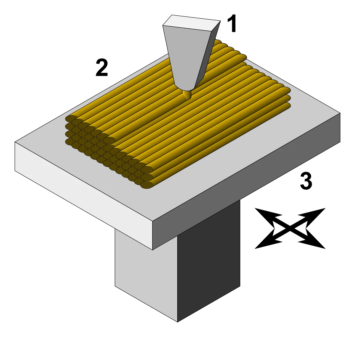
A 3D printer is a computer-controlled machine that builds a physical object from a digital file through successive layers. This additive manufacturing method places material only where the sliced model specifies, unlike a subtractive process that cuts material from a larger block. The U.S. Department of Energy describes the same model-to-layer sequence as the basis of 3D printing.
This guide covers consumer and desktop machines. It focuses on filament extrusion and resin vat photopolymerization, the two process families a home user is most likely to encounter. The next question is how a 3D printer turns the model into an object.
How does a 3D printer turn a digital model into a physical object?
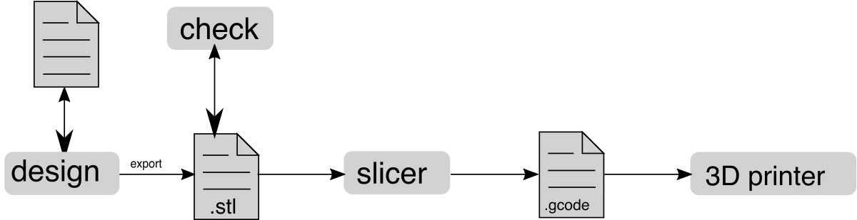
A 3D printer turns a digital model into a physical object through five steps: obtain the model, slice it, prepare the machine, build the layers, and finish the part. The slicer converts geometry into cross-sections and machine instructions. The printer controller then coordinates material delivery, light exposure, and build-platform movement as required by the selected process.
The workflow begins with the model, moves through slicing and machine preparation, and ends with layer construction and finishing.
- Create or obtain a printable 3D model.
- Slice the model with a compatible printer profile.
- Prepare the build surface and printing material.
- Build each cross-section in the specified order.
- Remove, clean, and finish the completed part.
The same general flow from digital design and slicing through printing and post-processing appears in HP’s 3D-printing explainer. Every job therefore starts when the user creates or obtains a 3D model.
1. Create or obtain a 3D model
A 3D printer needs digital geometry before building a part. A user can design that geometry in computer-aided design software, capture it with a 3D scan, or download an authorized model. The file must describe closed surfaces the slicer can interpret.
STL, OBJ, and 3MF are three common file containers. STL primarily records surface geometry, while OBJ and 3MF can carry additional model data. These formats appear in the design-to-print workflow documented by Formlabs. Compatible software must then slice the model into machine instructions.
2. Slice the model into machine instructions
A slicer divides the 3D model into layers and generates instructions for the selected printer and material profile. The user first chooses orientation and layer height, then sets walls, infill, and supports where the process requires them. The software uses those choices to calculate how each cross-section will be formed.
FDM output describes nozzle paths, extrusion, movement, and temperature commands. Resin output contains layer images or exposure instructions for the printer’s optical system. Many FDM machines accept a form of G-code, but that term does not describe every resin job file. A compatible output format matters because the printer controller must read each instruction in sequence. Slicing therefore connects model geometry to the next stage, printer preparation.
3. Prepare the printer and material
Printer preparation matches the build surface, material, and machine state to the sliced job. The exact checks come from the printer manual and the selected material profile.
Preparation covers the machine state, build surface, material, and sliced profile.
- Inspect the machine and complete model-required leveling or calibration.
- Clean and secure the build plate or build surface.
- Load compatible filament or fill the resin vat as instructed.
- Confirm that the sliced profile matches the machine and material.
Automatic leveling does not remove every preparation task, and one calibration routine does not fit every printer. The prepared machine can now build the object one layer at a time.
4. Build the object one layer at a time
The printer forms one cross-section, changes position by one layer, and repeats the cycle until the object is complete. Its controller reads the sliced instructions and coordinates the material-forming system with the build platform and motion system.
An FDM printer deposits softened thermoplastic along a planned path. A resin printer exposes selected areas of liquid photopolymer so that those areas cure into a solid cross-section. The machine then advances by the layer height set in the profile. That distance must remain within the machine and material limits; no single layer height applies to every printer. Each new cross-section attaches to the preceding one. After the final layer, the physical object still needs process-specific removal and finishing.
5. Remove and finish the printed part
A completed 3D print requires process-specific removal. An FDM part may need cooling and support removal according to the printer manual.
A resin part normally drains before removal and then follows the resin manufacturer’s washing and post-curing instructions. Uncured resin and cleaning solvent require documented controls. Five exposure stages appear in the CDC/NIOSH guide for desktop vat photopolymerization: resin dispensing; the print cycle; resin recovery; part cleaning; and waste handling. A cover alone does not settle ventilation or exposure. Those steps depend on the parts that make a desktop 3D printer work.
What parts make a desktop 3D printer work?
Desktop 3D printers share a controller and build platform, while their positioning and material-forming systems differ. The controller interprets the sliced file. Motors, rails, screws, belts, or optical components place each cross-section where the model requires it. The build plate supports the object during construction.
The comparison separates control electronics, positioning, material formation, and the build platform for each process.
| System | FDM example | Resin example |
|---|---|---|
| Control electronics | Mainboard coordinates heaters, extruder, fans, and X/Y/Z motion | Mainboard coordinates the light source, mask or laser, and Z-axis motion |
| Positioning system | Belts, rails, screws, and motors move the nozzle, bed, or gantry | A Z-axis mechanism moves the build plate between exposures |
| Material-forming system | Extruder, hot end, and nozzle feed and place thermoplastic | Resin vat, LCD mask or laser, and UV light source cure a cross-section |
| Build platform | Build plate receives the deposited first layer | Build plate holds the cured part as it rises from the vat |
Part names and layouts vary by printer architecture. A moving-bed FDM machine and a CoreXY machine divide X/Y/Z motion differently, while an SLA machine and an MSLA machine direct light differently. The first technology-specific question is how an FDM 3D printer works.
How does an FDM 3D printer work?
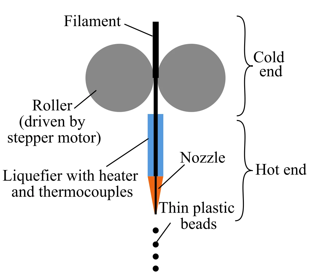
An FDM printer feeds thermoplastic filament through a heated nozzle and deposits it along sliced paths to form successive layers. Fused deposition modeling is commonly shortened to FDM. Fused filament fabrication, or FFF, describes the same broad material-extrusion family in consumer discussions.
The FDM material path follows this order.
- Filament unwinds from a spool toward the drive system.
- Drive gears in the extruder control the feed rate.
- The hot end softens the thermoplastic for deposition.
- The heated nozzle places a narrow bead on the build plate.
- X/Y/Z motion positions the next path and layer.
FDM is an additive process that extrudes melted thermoplastic filament through a heated nozzle, as Stratasys documents. The deposited path cools and bonds according to six variables: polymer; nozzle temperature; build-surface condition; cooling rate; orientation; and profile. Those variables prevent a universal strength or precision claim.
The first layer anchors the part to the build plate. Later layers follow the sliced perimeter, interior, and support paths. The controller repeats the motion and extrusion commands until the FDM object reaches its final height. A resin 3D printer works differently because light forms each cross-section.
How does a resin 3D printer work?
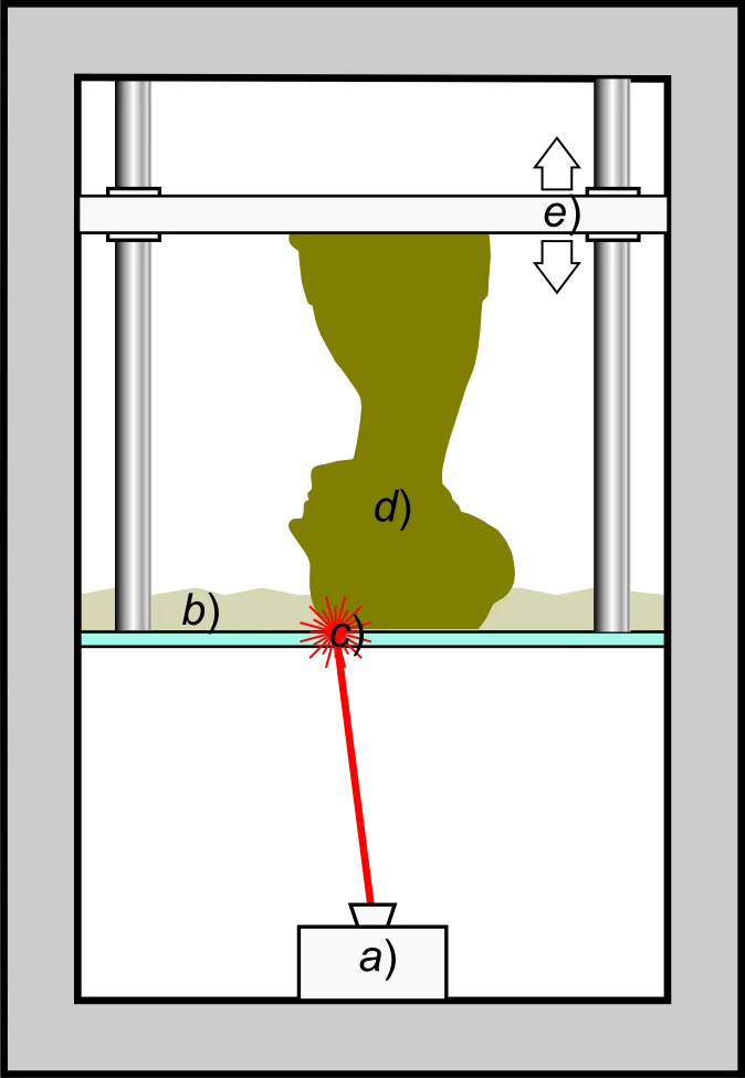
A resin printer selectively exposes liquid photopolymer to light so each layer solidifies against the build surface. This additive process is called vat photopolymerization because the uncured material sits in a resin vat during printing.
SLA, DLP, and MSLA form the layer with different optical systems. SLA traces the cross-section with a laser. DLP projects the cross-section with a digital projector. MSLA, often called LCD resin printing, places an LCD mask between a UV light source and the vat so selected pixels transmit the layer pattern. All three methods use light to cure liquid resin, as Formlabs explains.
An inverted desktop resin cycle follows this order.
- The build plate positions itself one layer above the vat window or release film.
- The laser, projector, or masked light exposes the selected cross-section.
- The cured layer separates from the vat surface during the release movement.
- The build plate repositions so liquid resin can cover the next layer area.
- The printer repeats exposure and release until the part is complete.
The printed object then needs the washing and post-curing procedure specified for that resin. Pixel size, light distribution, layer height, resin chemistry, support design, and release forces all affect the result, so a technology label alone does not prove detail or accuracy. Those variables frame how FDM and resin 3D printers differ.
How are FDM and resin 3D printers different?
FDM places softened thermoplastic along a path, while resin printing cures a scanned or projected cross-section in liquid photopolymer. Both methods build successive layers, but they use different feedstocks, machine systems, support workflows, and finishing steps.
The comparison tracks feedstock, layer formation, supports, finishing, and workspace controls.
| Dimension | FDM | Resin |
|---|---|---|
| Feedstock | Thermoplastic filament on a spool | Liquid photopolymer in a resin vat |
| Layer formation | A nozzle deposits material along sliced paths | A laser, projector, or masked light cures selected areas |
| Supports | Sliced support paths print with model or support filament | Supports cure with the part and connect it to the build plate |
| Post-processing | Cooling, part removal, support cleanup, and optional surface work | Draining, washing, support removal, and specified post-curing |
| Workspace and handling | Heat, moving parts, material storage, and process emissions require model-specific controls | Uncured resin, solvent, UV curing, spills, and waste require product-specific controls |
| Project characteristics to verify | Build volume, nozzle and material compatibility, orientation, profile, and acceptable layer appearance | Build volume, optical system, resin compatibility, orientation, supports, and finishing requirements |
Detail, strength, speed, and dimensional accuracy depend on the printer, material, orientation, part geometry, layer settings, supports, and post-processing. A process name does not supply those measurements. A small resin part and a large FDM part also make poor speed comparisons because the cross-sections and workflows differ.
Project requirements must therefore come before a winner label. Evaluate project, material, workspace, compatibility, and total cost of ownership in Resin vs Filament 3D Printing: Printers, Materials and Workflow to match your project needs. Those process families lead to the types of 3D printers used at home.
Which types of 3D printers are used at home?
Most consumer desktop choices fall into filament extrusion or vat-photopolymer resin families. Each family contains multiple machine layouts, materials, and control systems, but the layer-forming mechanism defines the main group.
The two home-oriented families differ by whether they deposit thermoplastic or cure liquid photopolymer.
- FDM or FFF printers feed thermoplastic filament to a heated nozzle, then deposit each path on a build surface.
- SLA, DLP, and MSLA resin printers expose liquid photopolymer in a vat, then separate and reposition each cured layer.
FDM and MSLA are common terms in consumer product catalogs. SLA and DLP also appear in desktop and professional systems, so the product documentation must identify the actual optical process. Powder-bed and metal systems exist, but they fall outside this consumer and desktop guide. Within the two home-oriented families, desktop 3D printers use process-specific materials.
What materials do desktop 3D printers use?
FDM printers use compatible thermoplastic filament, while resin printers use compatible liquid photopolymer resin. Material compatibility depends on the printer hardware, manufacturer guidance, selected profile, and conditions around the machine.
Common FDM classes include rigid general-purpose filaments, temperature-sensitive engineering filaments, and flexible filament.
- PLA filament is a common profile option on consumer FDM printers.
- PETG filament requires a matching hot-end, build-surface, and cooling profile.
- ABS or ASA filament may add enclosure, ventilation, and temperature-control requirements.
- TPU filament requires an extrusion path and settings that support flexible material.
Common resin classes cover general models, altered mechanical behavior, and casting workflows.
- Standard resin covers general model and prototype categories.
- Tough and flexible resins target different mechanical behavior.
- Castable resin is formulated for a compatible casting workflow.
An FDM printer’s hot end, bed, enclosure, and material profile set its operating range. A resin printer needs a compatible wavelength, exposure profile, vat system, and manufacturer-approved procedure. The material label alone does not establish printer compatibility. The remaining questions cover what else a beginner needs to know about how 3D printers work. You can explore institutional workflows in the 3D Printing for Business & Education hub.
What can a desktop 3D printer make?
A desktop 3D printer can make prototypes, custom fixtures, educational models, and hobby parts when the model, material, build volume, and safety requirements fit the machine. The Formlabs 3D-printing guide documents prototyping and tooling applications across multiple 3D-printing technologies. A 3D printer cannot make every object or use every material; the required part properties and documented machine limits decide whether a project fits.
What else should a beginner know about how 3D printers work?
A beginner needs to understand file preparation, print time, material limits, and workflow requirements before choosing a process. The first dependency is whether a 3D printer needs a computer.
Does a 3D printer need a computer?
A 3D printer usually needs a computer or connected device to prepare and transfer a sliced file, but many printers can run the job afterward from local storage or a built-in controller. File preparation and print execution are separate tasks.
The slicer runs on a supported computer, tablet, browser service, or printer interface. The file may travel by memory card, USB, cable, Wi-Fi, local network, or a vendor service. After the controller receives the complete job, some printers operate without a continuing computer connection. Model documentation defines transfer, offline behavior, Wi-Fi, and cloud support. It cannot predict how long every 3D print takes.
What determines 3D print time?
Part size, layer height, geometry, supports, settings, and printer technology determine 3D print time. The slicer estimate for the selected model, profile, material, and machine is more useful than a universal average.
The main print-time factors change either the number of layers, the work within each layer, or the printer’s operating sequence.
- Part size changes the amount of material and motion.
- Layer height changes the number of layers.
- Geometry changes path length or exposed area.
- Supports add printed or cured structures.
- Settings control movement, exposure, cooling, and pauses.
- Printer technology determines how each cross-section forms.
A slicer estimate is a forecast from the chosen model, profile, and machine definition. Workflow time can also include the warm-up stage, calibration, material setup, the wash cycle, the post-cure cycle, or part removal. The next limit is whether one 3D printer can use every material.
Can one 3D printer use every material?
No 3D printer uses every material; each machine supports a limited material family and operating range. FDM material compatibility depends on nozzle and hot-end limits, bed requirements, extrusion path, enclosure conditions, firmware, and an approved temperature range.
Resin compatibility depends on resin wavelength, exposure behavior, vat requirements, release-film requirements, the wash procedure and an approved profile. A bottle that fits beside the printer is not proof that its chemistry works with the optical system. Manufacturer documentation must confirm the material, profile, exposure controls and finishing steps before use. Those limits help determine which printing method fits the first project.
Which printing method fits your first project?
Choose the printing method based on the object and material behavior. Check finishing steps and workspace conditions next. Compare machines only after the first project supplies the requirements they must meet.
The decision branches connect part requirements, cleanup, workspace, and documented machine limits to the process choice.
- Functional, large, or simple parts point to checking FDM build volume, filament compatibility, orientation, and layer appearance.
- Small or detail-focused parts point to checking resin pixel or laser behavior, supports, orientation, and validated dimensional results.
- Handling and cleanup tolerance determines whether filament removal or resin washing, curing, solvent, and waste procedures fit the user.
- Ventilation and workspace conditions determine where the machine, materials, tools, and finishing equipment can operate under their instructions.
Neither branch selects a universal winner. A printer still has to match the required build volume, material, support workflow, software, maintenance, and documented operating conditions. Compare your options in the Best Desktop 3D Printers for Beginners by Project and Workspace guide.
A 3D printer is therefore a model-to-part system whose workflow, components, process, materials, uses, and documented limits determine whether it fits a project.